
Published on September 14th, 2026
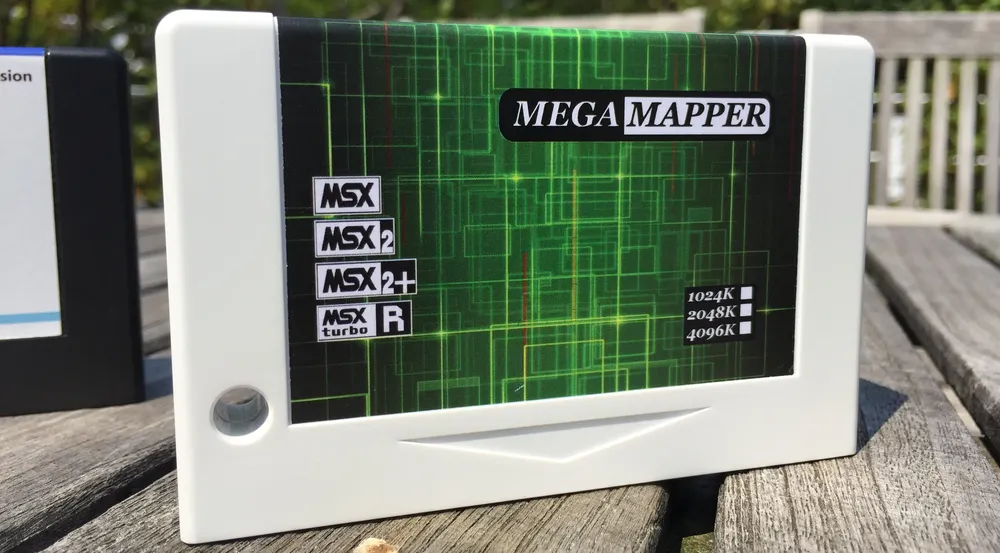
Back in 2016 I wrote a review of three memory mapper cartridges, and I put a short introduction at the top explaining how memory works on the MSX, just enough for the review to make sense. That introduction has outlived the review, so here it is as an article of its own, expanded this time with the part I left out originally: how the programmer actually drives all of this.
If you have ever wondered what "slot 3-2" means, or why MSX programmers get nervous about page 3, this is for you.
Slots
The CPU in MSX computers is the Zilog Z80 (or a compatible one). This processor can access only 64KB of memory at a time, so in order to use more memory the MSX uses a technique known as bank switching. The MSX has up to four memory banks of 64KB each, called slots.
It works like this: the Z80 address space is split up in four 16KB pieces called pages:
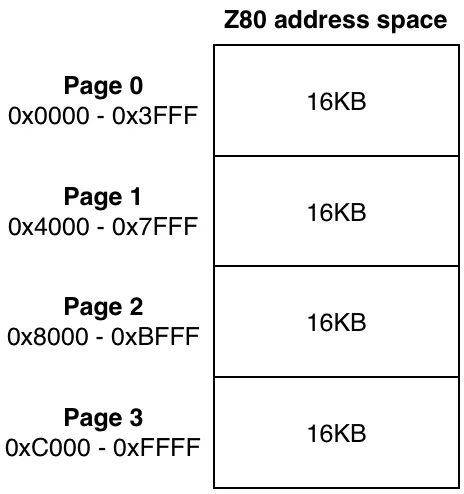
Then, using a hardware mechanism, the programmer selects what memory bank will appear on each memory page of the CPU. This means that page 0 of the CPU address space can be connected to page 0 from slots 0 to 3, page 1 of the CPU can be page 1 from slots 0 to 3, and so on.
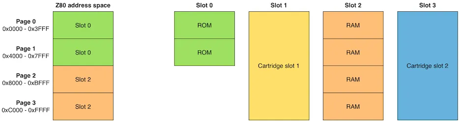
As an example, the Toshiba HX-10 (64KB model) has this memory configuration:
- ROM in pages 0 and 1 of slot 0
- RAM in pages 0 to 3 of slot 2
- Slots 1 and 3 are connected to the cartridge slots.
- Pages 2 and 3 of slot 0 are unused
When this machine boots into MSX BASIC it starts with this slot configuration:
All MSX generations support this kind of bank switching, from the most basic MSX(1) computer to the most powerful MSX turbo R.
We can easily see that using only these slots an MSX computer can have at most 256KB of total memory, after adding together ROM, RAM, and whatever we plug into the cartridge slots.
Selecting a primary slot
So what's the hardware mechanism I mentioned above? The mechanism is a single I/O port: A8h.
A8h is port A of the 8255 PPI, the same chip that scans the keyboard through ports A9h and AAh. Its eight bits are split into four pairs, one pair per Z80 page, and each pair holds a primary slot number from 0 to 3:
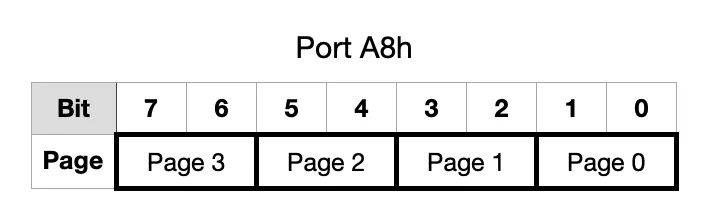
That is the whole mechanism. Think of A8h as a little panel with four knobs on it, one per page, each knob with four positions. Turn the "page 1" knob to position 2 and whatever lives in page 1 of slot 2 now answers to addresses 4000h–7FFFh. Nothing has been copied anywhere; you have just changed what slot the Z80 is seeing in that page.
Unlike most MSX hardware registers, A8h can be read back, which means you can modify one page and leave the other three alone without keeping notes:
    in   a,(0A8h)
    and  11110011b      ; clear the page 1 field
    or   00000100b      ; slot 1 into page 1
    out  (0A8h),a
Two very important things that you (the programmer) need to take into account when switching slots:
Page 3 holds the stack and the system variables. Everything from C000h up is RAM that the BIOS, BASIC and MSX-DOS are actively using. If you switch a different slot into page 3 and then so much as execute a CALL, the Z80 pushes a return address into whatever is now sitting there and your program is over. Code that has to touch page 3 needs to be extremely careful about this.
Page 0 holds the BIOS, including the interrupt handler. The Z80 interrupt vector on the MSX lands at 0038h, which is in page 0. If you switch page 0 away from the BIOS without a DI first, the next time an interrupt happens (50 or 60 times per second) the CPU jumps into whatever happens to be at that address now, and your program is over.
Subslots
The second generation of MSX computers extended the concept of slots in order to allow for more memory. From MSX2 and up a slot can be extended in order to support up to four subslots (also called extended, secondary, or expanded slots).
The Z80 address space is still split into four 16KB pages, and each of them can be connected to any slot from 0 to 3 as before. However, when a page is connected to a slot that is extended we have to also specify a subslot.
As an example, the Panasonic FS-A1F. This machine is a basic MSX2 with 64KB of RAM in subslot 3-0, the A1 Cockpit application in ROM (subslot 3-1), and a floppy disk drive. It has the following slot configuration:
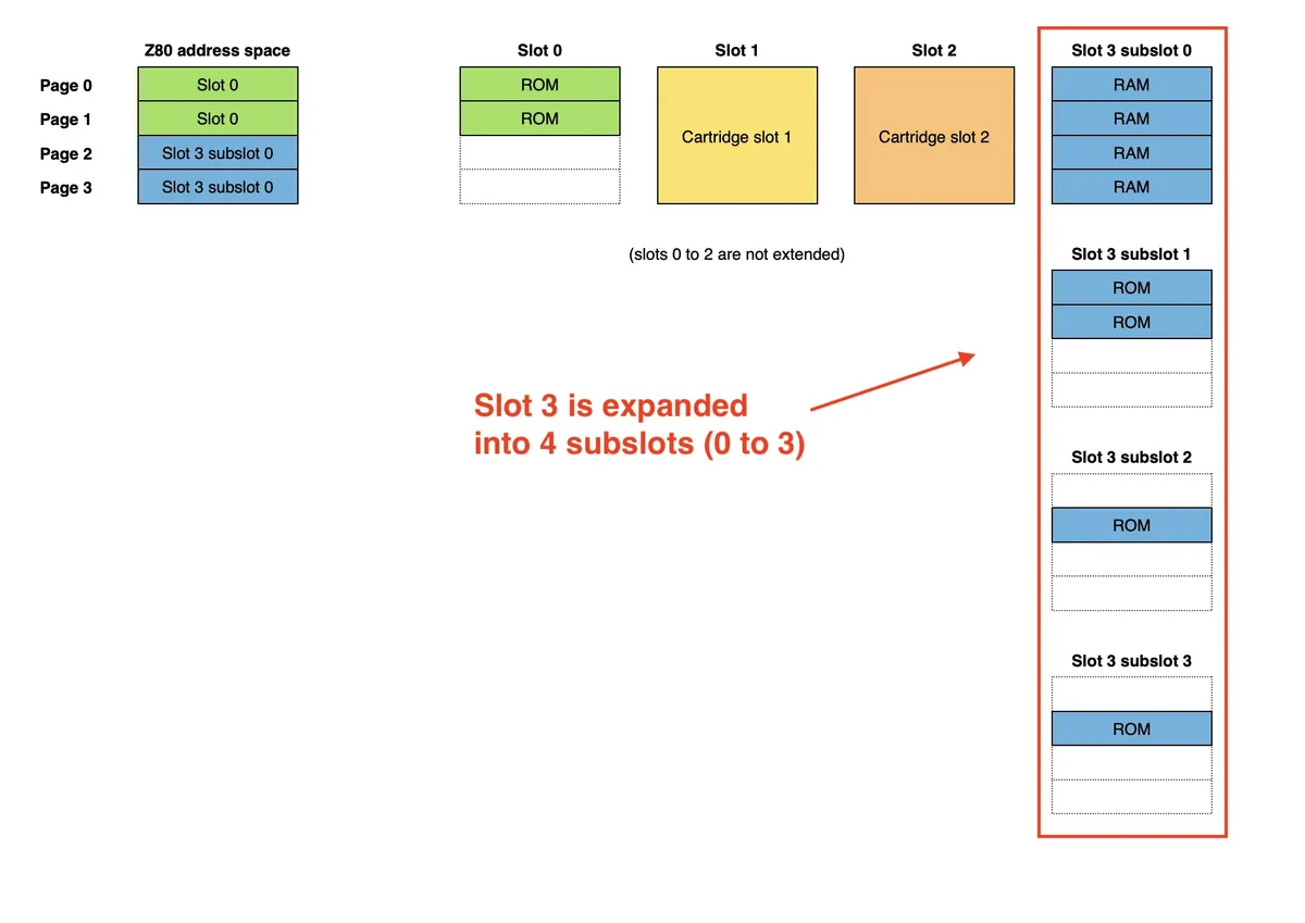
Slots that aren't expanded are known as primary or basic slots. In the case of the Panasonic FS-A1F, slots 0, 1 and 2 are primary, and slot 3 is expanded.
In the graphic above you can see that slots don't need to be full:
- Slot 0 in the FS-A1F only holds addresses 0000h-7FFFh (the MSX BIOS)
- Slots 1 and 2 don't hold anything unless there's a cartridge plugged in them
- Slot 3-0 holds 64Kb of RAM (addresses 0000h-FFFFh)
- Slot 3-1 holds 32Kb of ROM (addresses 0000h-7FFFh)
- Slot 3-2 and 3-3 each hold 16Kb of ROM (addresses 0000h-3FFFh)
Expanded slots cannot be expanded any further.
A simple calculation gives that if all slots were expanded and full (which never happens), an MSX2 computer (or higher) could have at most 1MB of total memory: 4 slots x 4 subslots x 64Kb each = 1024Kb
Using slots and subslots works well enough for the applications that come integrated with the computer and for system ROMs. However, having several subslots full of RAM wouldn't be very helpful because we can only connect a given slot/subslot page to the same page number of the CPU address space. Locating and using all the RAM in this situation is complicated for the programmer because of all the bank switching required.
Selecting a subslot
Subslots are where the MSX memory system stops being tidy.
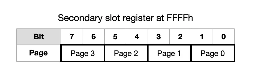
You would expect a second I/O port next to A8h. There isn't one. The secondary slot register is memory-mapped at address FFFFh, and it lives inside the expanded slot itself. A machine with two expanded slots has two completely separate FFFFh registers, and which one you hit when you write to FFFFh depends on which primary slot is currently selected in page 3.
The bit layout is the same as A8h, with subslot numbers instead of slot numbers:
Reads come back inverted
FFFFh is readable, but it returns the one's complement of what was written. If you wrote 0000111b you will read 11110000b. CPL or XOR 255 converts that number to the actual value that the register holds.
This looks like a hardware bug, but it isn't. It's the standard way to detect whether a slot is expanded or not: write a value to FFFFh of the slot, read it back, and if you get the complement there is a secondary slot register answering. If you get your own value back unchanged, you are reading plain memory and the slot is not expanded.
Because reading is that awkward, the BIOS keeps a mirror in RAM:
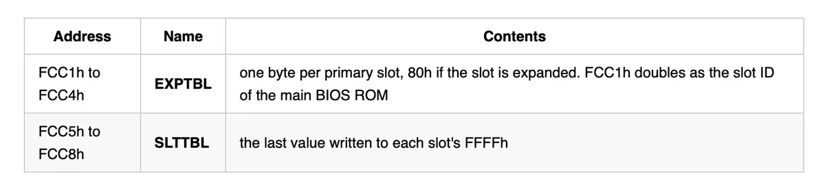
Read SLTTBL when you want to know the current configuration. Never try to read FFFFh for that.
The slot ID byte
Once subslots exist, "slot 3" is no longer enough to identify a location, so the BIOS packs both numbers into one byte:
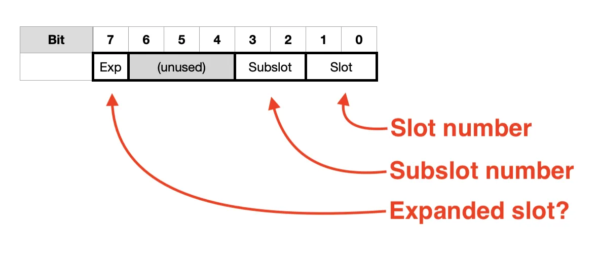
If EXP is 1, then bits 3-2 hold the subslot number. If it is 0, then the slot ID byte refers to a primary slot (not expanded), and bits 3-2 can be ignored.
All the slot-related BIOS calls use this slot ID format. For example, slot 3-2 of an expanded slot 3 is 10001011b = 8Bh.
Better let the BIOS handle it
Unless you have good reasons to do the slot switching yourself, it's safer to let the BIOS handle this complexity. There's a set of routines for this purpose:
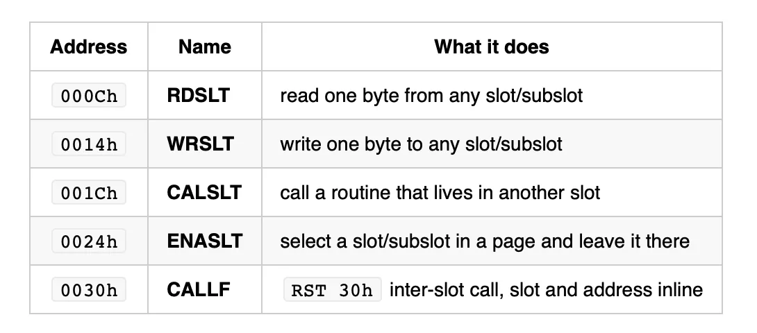
All of them take the slot ID byte, and all of them handle switching page 3 correctly.
There is a catch worth knowing: RDSLT and WRSLT disable interrupts and perform the entire slot switch for a single byte. They are perfect for probing hardware and disastrous inside a loop. When you are about to read a lot of something, call ENASLT once and then access memory normally.
Memory mappers
In addition to these, the MSX2 standard defines an optional extension to support more memory: the memory mapper. Most (if not all) the MSX2/MSX2+/MSX turbo R computers with more than 64KB of RAM use this.
The mapper consist in a collection of RAM blocks, each of them 16KB, called segments. Depending on its size it can contain from 4 to 256 of these segments, always in powers of two: 4, 8, 16, 32, 64, 128 or 256 segments for a total of 64, 128, 256, 512, 1024, 2048 or 4096 KB.
A mapper occupies the four pages of the slot or subslot to which it is connected, and there's a hardware mechanism that allows the software to select what mapper segment is connected to each page of the slot:
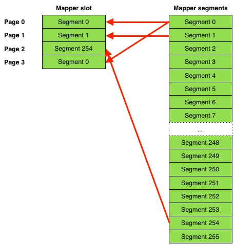
Note that the same mapper segment can be assigned to more than one page simultaneously. In the example above, segment 0 is assigned to page 0 and 3 at the same time. This means that both pages contain a mirror of each other.
The Philips NMS 8250 is an MSX2 machine with a 128KB memory mapper connected to subslot 3-2. A possible memory configuration under MSX BASIC could be this:
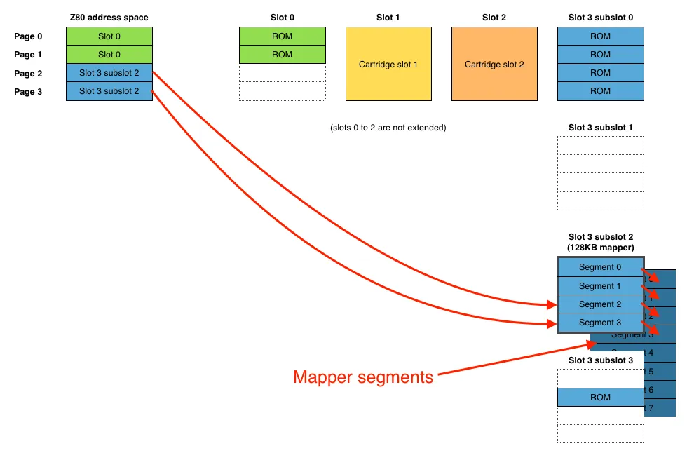
The memory mapper is perfect for storing program data because we can very easily swap the visible segment(s) and put them in any page of the Z80 CPU.
Note that there can be more than one memory mapper in an MSX computer. MSX-DOS2 supports up to 8 of them. As a curiosity, after accounting for slots assigned to ROM an MSX can have a theoretical maximum of up to 52MB of RAM.
MSX1 computers can use memory mapper cartridges, but since the mapper is an MSX2 extension, software written with the MSX1 specification in mind will only be aware of the active 64KB, regardless of the mapper size. Some applications written for MSX2 and higher (such as the MSX-DOS2 operating system) will run just fine on an MSX1 and will be able to use the mapper without issues, as long as they don't require any other hardware not present in the MSX1.
Selecting a mapper segment
The mapper's "hardware mechanism" is four I/O ports, one per Z80 page:
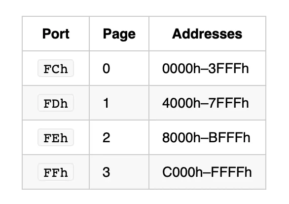
For example, to put segment 12 of the mapper in page 2 (8000h-BFFFh), just write 12 to port FEh.
Note that writing to the mapper ports doesn't affect what slot/subslot the Z80 sees in that page. Take the memory diagram for the NMS 8250 above: under MSX-BASIC, that machine has slot 0 (MAIN ROM) selected for the Z80 pages 0 and 1, and expanded slot 3-2 (the internal mapper) on pages 2 and 3. If we write any value to port FCh, nothing will change in the Z80 address space until we also map expanded slot 3-2 in page 0.
Some things that we need to take into account:
Treat the mapper ports as write-only. Some internal mappers will let you read a port back, but external ones generally won't, and reading is explicitly discouraged in the standard, so don't rely on it. Keep your own copy in RAM of what you last wrote.
They are not empty at boot. After a reset the BIOS sets segment 3 in page 0, segment 2 in page 1, segment 1 in page 2 and segment 0 in page 3. So the plain 64KB of RAM that a stock MSX2 appears to have is just mapper segments 3, 2, 1 and 0 arranged in that order.
Only the low bits matter. A 128KB mapper has 8 segments and only decodes 3 bits, so writing 9 leaves you looking at segment 1.
Every mapper in the machine sees every write. The ports are not per-slot. If you have an internal mapper and a mapper cartridge, a single out (0FEh),a changes that segment number into both of them, simultaneously. They don't conflict, because only one of them is visible in page 2 at any moment. But it does mean the hardware cannot tell "what segment is currently selected in this mapper". That is something that the software needs to keep track of.
And the obvious one: port FFh is exactly as dangerous as address FFFFh, for exactly the same reason. Changing the segment in page 3 pulls the stack and the system variables out from under the running program. MSX-DOS2 feels strongly enough about this that its own "set the segment for page 3" routine is deliberately a no-op.